Includes affiliate links that help offset our expenses at no cost to you.
I built this modular CNC controller to run a variety of different machines in my shop. My first application is to replace the old controller on my CNC Shark router but I wanted the flexibility to reuse the same hardware on different machines, so I came up with a standard connector layout that will let me swap the controller and power supply for different needs. Initially I’m using the DDCSV1.1 Control Panel but I could someday replace it with a different standalone controller or an Ethernet SmoothStepper and Mach3 or Mach4 software.
The second video covers details of wiring and configuration of the CNC controller.
DDCSV1.1 Control Panel Documentation
Here is the DDCSV1.1 User Manual that contains a wealth of information about this panel, including details of wiring and operation.
Construction Details
Here are links to most of the parts that I bought on Amazon.com:
- DDCS 4 Axis Control System
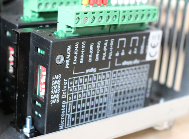
- KL-5056 20-50VDC 5.6A Digital Bipolar Stepper Motor Driver – 32 bit DSP Based
- BUD Industries AC-405 Aluminum Chassis, 7″ Length x 7″ Width x 2″ Height, Natural Finish
- 2P5T 2 Poles 5 Position Rotary Switch
- Ferrule Crimp Tool Kit
- Remington Industries 18UL1007STRKIT UL1007 18 AWG Gauge Stranded Hook-Up Wire Kit
- Connectors Pro DB37 Female D-Sub Solder Type Connector, 10-PK
- D-Sub Hex Head Screw with Nut 4-40UNC
- 400W 36V Switch Power supply, DC power S-400-36 11A
- URBEST Inlet Module Plug 5A Fuse Switch Male Power Socket 10A 250V 3 Pin IEC320 C14
- US 3 Pins Power Socket Plug Black AC 125V 15A
- Blue Sea Systems Push Button Reset-Only CLB Circuit Breakers with Quick Connect Terminals
- uxcell DB25 25 Pin Female to Male Solder Type Adapter Connectors 5 Pair
- 12mm 5 Pin Aviation Connector Male Female
I laid out the openings in the aluminum case for the pendant and cut out the front panel using my Dewalt scroll saw. The end panel couldn’t be cut on the scroll saw so I used a nibbling tool to make the openings for the USB and DB37 connectors. I also added aluminum L channels on the back of the case in order to mount the control panel:


The wiring was pretty straightforward but there were a lot of connections, and because most of them used screw terminals I used crimp ferrules on the wire ends. This was the first time I had used crimp ferrules and they worked great, much more secure and neat looking than bare wire ends.

The signal wiring is all 22-AWG stranded wire, and here’s the pinout that I used on the DB37 connector:

I couldn’t find an off-the-shelf enclosure of the size that I wanted for the power supply module so I made my own from aluminum sheet using my ShopFox box and pan brake and plate shear. I ran the AC power from the switched inlet to a 10A circuit breaker, and then to the two power supplies. I also added an AC outlet to run the cooling pump for my 2.2KW water cooled spindle. On the 36V 11A supply for the stepper motors, I added a 22,000 microfarad capacitor to help absorb the current spikes from the stepper drivers.

The output current of the stepper drivers is configured using DIP switches and I have them set for 2.8A output current, which is the rating of the stepper motors in my CNC router. I could have used a larger power supply and drivers that would be sufficient to run the larger 6A stepper motors I plan to use on the milling machine, so that a single power unit could run either machine. But that would require changing the DIP switches when moving it between machines, which is inconvenient and error-prone so I chose to dedicate this power unit to running medium-size steppers and to build a separate one for the mill. I could still use this power unit on another machine such as my metal lathe, as long as I use stepper motors with similar current requirements.
I set the stepper drivers for 1/16 microstepping, and the CNC Shark HD router’s X-Y lead screws have multi-start threads with a lead of 0.5 inch or 12.7 mm per rotation. So with 200-step stepper motors, the pulses per millimeter are calculated as 200 * 16 / 12.7 = 251.969. This number must be entered into the settings page on the CNC controller. The Z-axis lead screw has a finer lead of 0.25 inch or 6.35 mm per rotation so its setting is 503.937 pulses/mm.
Software
I use AutoDesk Fusion 360 to model 3D parts and to generate CNC toolpaths using its CAM capability. AutoDesk makes this software available FREE to hobbyists and it’s very powerful. It has a steep learning curve but there are lots of tutorials available for it. I initially started using Fusion 360 with the original controller for my CNC Shark router, but unfortunately it lacked a post-processor to generate compatible G-code so I wrote my own post-processor for it and the resulting G-code works with the original CNC Shark controller as well as the DDCSV1.1 control panel that I’m using now. To use this post-processor with Fusion 360, follow these steps:
- Right-click on this link and save the target file to a directory of your choice, and rename the file with a .cps extension. The post processor is written JavaScript and it includes an open-source license that lets you use and copy it freely, but entirely at your own risk.
- In Fusion 360 select the CAM workspace, create a milling operation and generate a toolpath from it. You can find online help on CAM if you don’t know how to get that far.
- Once your toolpath is generated, select it and either right-click to select the Post Process menu, or select the Post Process button on the toolbar at the top. Again you can find online help on post-processing if you need it.
- In the Post Process dialog, next to ‘Post’, click the drop-down and select ‘Choose from library…’. On the left side under ‘My Posts’ select ‘Local’ (it may already be selected), and up above click the ‘Import’ icon. Browse for the .cps file that you saved in the step above, and press Open. You should only have to do this once – thereafter it should show up as an available post when you select the My Posts / Local item on the left.
- Pressing the Post button will generate G-code that should work on the DDCSV1.1 controller, as well as on the original CNC Shark controller.
- Transfer the resulting G-code file to the controller and run it. I strongly recommend “cutting air” at first, to test the G-code before performing actual machining with it. My usual technique is to raise the Z axis well above the part and then zero it out, so that I can test the code without actually cutting anything until I believe it’s correct.
Coolant Control
The latest revision of this post-processor supports the M8/M9 output, which will be activated while running any toolpath with any Coolant setting other than ‘Disabled’. This output can be used to control a coolant pump for liquid cooling, an air valve for air blast cooling, a vacuum for dust removal etc. It has limited current capacity so an external relay is required for controlling any high-current loads. Please refer to your DDCS controller manual for documentation of the M8/M9 output.
You may email me at Jay (at) BrainRight (dot) com with reports of any problems or requests for enhancements to this Fusion 360 post-processor, but I provide it at no charge with no guarantee of any kind and I may or may not respond to requests for changes.